@timtom1 wrote:
Hi guys
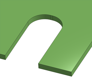
I want to cut this picture out of a 0.2mm brass sheet, how do I convert it to 3d? some parts raise up a few mm than other bits.
Thanks
Tim

Posts: 4
Participants: 4
@timtom1 wrote:
Hi guys
I want to cut this picture out of a 0.2mm brass sheet, how do I convert it to 3d? some parts raise up a few mm than other bits.
Thanks
Tim
Posts: 4
Participants: 4
@Remmy wrote:
I'm trying to import a very large stl file into MeshCAM with topographical data for a large area. It's 12 of the largest segments allowed from http://jthatch.com/Terrain2STL/ that I've assembled together in Meshmixer. The file size is 2.3Gb and I'm having trouble importing the stl into MeshCAM. I was able to import two sections with a file size of about 370Mb however. Does anyone know if there is a file size limit that I should be shooting for? @Randy perhaps?
Posts: 3
Participants: 2
@TotallyFred wrote:
I have a doubt... When setting up plunge & feed rate, overlap, depth of cut and material information into gwizard and MC, there is no way to differentiate the "first cut" from subsequent passes into the material.
What disturbs me is that a first cut will essentially be a 0% overlap and tool deflection (driving shatter etc) will be different thanfrom subsequent overlapped cuts. This is particularly relevant to the roughing phase.
I could not find any way to specify that difference in feed and plunge rates.
It seems the safe way is to always assume 0% overlap in gwizard but
- this yields very slow feed rates and long jobs
- feeding too slow seems as bad as too fast (heat)Am I missing something or overanalyzing this ?
Thanks!
Posts: 5
Participants: 3
@adamstag wrote:
Hey guys,
I have the basic ball/endmill 0.125"/0.063" tools that I bought with my Nomad and wanted your feedback on drilling small holes. After surfing this forum I found some tools that seem perfect since they fit right into the chuck and can get into holes that the 0.063" milling tools can't get into.Now I am working on using these tools and have a couple questions about how to properly drill using MeshCam with the Nomad,
-Is there a good way to input drill settings as a new tool? So far I have just been adding tools and calling them ballmills with small values for all of the settings irrelevant for drilling, but is there something more drill oriented?
-In the drilling menu are there some guidelines I should follow for setting RPM and plunge rate? I found this site, but wanted to hear from someone with some experience before diving in: http://www.daycounter.com/Calculators/GCode/Feed-Rate-Calculator.phtmlThanks!
Adam
Posts: 1
Participants: 1
@Jexoteric wrote:
I was cutting out a part from 1/4" MDF and didn't set any supports in Meshcam as I thought they wouldn't have been needed, but found out the program created the tool path cutting the largest features first, which was a circular perimeter around the part, and then moved to the smaller inner features.
A. Why would the program work from the outside in, forcing you to add support features that otherwise would not be needed and slowing down cutting?
B. Is there a setting that flips this, so it will cut any interior features first and then cuts the features that will remove the part from the rest of the stock?
Posts: 2
Participants: 2
@timtom1 wrote:
Hi guys
I've been playing with my meshcam settings and have forgot the perameters I had to get a smooth finish on my parts.
Here are my settings and finished part. Is the step over too large?
Thanks
Tim
Posts: 6
Participants: 2
@mikep wrote:
There's a new beta for MeshCAM 7 on the meshcam site. Looks like they've been working hard on UI issues. It's only the first beta, but looks like there are at least a few new features in there.
Posts: 1
Participants: 1
@AlanCart wrote:
I was very excited to see that MeshCAM7 allows for contour and pocketing operations. It wasn't until i plugged into my Shapeoko 3 XL that I realized MeshCAM7 outputs .egc files as opposed to .nc files regardless of which machine is selected. Has anyone gotten around this? I dug through the settings and wasn't able to find anything.
Posts: 13
Participants: 6
@ttumkaya wrote:
I've been trying to cut a piece which has parts in 3 different depths: 1.5mm ,1mm and 0mm.
For some reason, MeshCAM toolpath is doing parallel finish on all the surface area. And when I switch the parallel finish off, it does not cut the surface which has to be cut (1.5mm in depth). I'm attaching screenshot for the settings and an .stl file of my design.
Any help is greatly appreciated!
Thanks,
OSAR 16 chambers_flyLayer .STL (118.4 KB)
Posts: 3
Participants: 3
@DanoInTx wrote:
Hello, I replied to the message down below about GWizard integration with Meshcam not working on a Mac, but maybe my reply is being skipped over since my issue is actually on a PC. Basic issue is I create a tool in GWizard, then use the button in GWizard to export that tool to Meshcam. In Meshcam I get no button to paste my tool data. I can paste the data into a text document, so I know it's being copied to my clipboard, but Meshcam doesn't register for some reason. This is on a three day old PC running Windows 10 with fresh install of GWizard and fresh install of Meshcam 6 and 7 beta. Sorry to double post this, but if someone on a PC has found a solution I don't want to get overlooked on a Mac thread.
Thanks,
Dan
Posts: 7
Participants: 3
@PDG wrote:
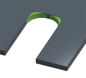
I was wondering if anyone knows if there is a way to mill these grooves in one pass. When I mill this part after running it through MeshCAM, there a many retracts which take up a lot of time. I was hoping to be able to have the mill follow the contour and cut those in one pass. It would be so much quicker. Is this perhaps just a limitation of MeshCAM? Are there other CAM packages that handle this sort of thing differently?
Posts: 5
Participants: 3
@NinjaLlama wrote:
I am having issues when I am cutting a 2d rectangle using meshcam. The code will run until it has the entire edge cut out then it will move out farther into stock that has not been machined and try to plunge down for some reason. This jams the machine and ruins the part. Any thoughts on what is causing this?
Posts: 2
Participants: 2
@rayjneal wrote:
I just got my nomad today. I am trying to create a button I designed. When i generate auto tool path, it does not cut the piece from the stock, as shown in the picture. Please advise. Thanks for the help.
Posts: 20
Participants: 4
@bheffernan wrote:
Hi all,
I am a noob to CNC and my Nomad and am trying to prototype a piece for work. I'm struggling with a design element. Anyone have advice?
The final piece is an 8" x 3" phone cradle made in a rubber-like plastic (see 1st pic of what we are imitating). I'm trying to generate a file that can be provided to a manufacturer who will make a mold and fabricate the pieces. Making an STL of the basic cradle in Inventor was easy enough. The element causing difficulty is a logo which should end up raised up from the surface like the IPC is in the pic. Instead of IPC there should be a globe there, raised only about .05"/120mm off the surface of the part.
I made the globe as a separate part in Inventor and wanted to export it to STL to open in MeshCAM and mill it on the Nomad in RenShape just to see if it looked OK. If it does, I'll put it onto the larger part. The diameter of the globe is only 2" / 50mm so it's small. The groves are .08" wide and the plan was to use a .0625" bit. I also have a .0312", both are ball (MeshCAM wizard recommended flat). MeshCAM keeps returning paths that don't show any cutting for the grooves and the time to completes are <1 minute.
Any thoughts on why it won't generate a working toolpath or advice on what to try?
Thank you,
of the final piece.
Brendan
Posts: 2
Participants: 2
@rayjneal wrote:
I've successfully cut this geometry twice now, but both times it has failed to cut the pockets in the four corners. Corner holes are 3.3mm, the .125" endmill calculates 3.175mm.
Do I need to use a smaller endmill?
Attached are the files.
bb_door_front_v2_for_125_cutter.stl (86.5 KB)
bb door frt.mcf (83.1 KB)
front panel top side.nc (380.8 KB)
Posts: 2
Participants: 2
@abrackney wrote:
When defining my stock, I lock stock dimensions and then usually set my Z position to 0 as shown in the image below. You can see the Z top position is at .02. It seems like the default is .01 for top and bottom Z.
I guess I am wondering if I am setting this correctly?
Posts: 8
Participants: 4
@bartok wrote:
Hello everybody.i am sorry for my bad English but I will try to do my best.
Is it a setting inside my meshcam file or inside carbide motion? Thanks, and now I have to design my own dust shoes and my clamping board!
Yesterday I make my first cutting operation in a piece of 15mm plywood sheet . I was a little bit frightening at the beginning but everything goes good! Expect one thing.
Whene I put the zero point, I was thinking the zplate go up a little bit before start the tool path but no... And every time the router make a rapid move , he make a little track ( over 1mm) inside my first cut.....
Posts: 3
Participants: 3
@Cereza wrote:
Hello,
I am trying to cut this piece with a Nomad. The piece is part of a DXF file that I acquired (Brian Law's first clock). Pawl.mcf (39.3 KB)
This is not a problem of zeroing Z. The top part of the piece is cut without issues.
With my settings, MeshCAM generates code that breaks the tool in the middle of the job. I can see why with bCNC. There are two sets of toolpath curves and each set has a depth equal to half the stock height. The deeper set is offset with regard to the first (Why?). When the second set is being cut, the tool plunges and then moves horizontally but there is still too much material around it and the tool breaks.
How can I correct this problem? Is it a question of the MeshCAM parameters I'm using? Is it a problem with the DXF files? Or am I missing something obvious?
Note: I scaled the DXF file by a factor of 0.5 before feeding it to MeshCAM.
Thanks,
Ric
Posts: 6
Participants: 2
@DylanRose wrote:
Well i'm finally getting to the point where I almost feel i might, possibly, understand some of the settings, to some degree, and can sort of predict, in some cases, the feeds, speeds, and everything else without destroying the material or the blade. Sort of. So that's progress! ha
My question is about parts that have some considerable clearing as well as some fine detail in some areas as well. I picked up a few smaller bits (1/16, 1/32 & 1/64) and have had a good time experimenting with each, but one hurdle i'm facing is that is I have a job that had both lots of clearing as well as fine detail, I can do a roughing pass with the 1/8 and a finishing pass with a 1/16 or smaller, but it still has to cover the entire surface of the stock which is really time consuming.
So say I've got a part with some internal corners and the roughing pass takes care of the general shape:
Then I want to finish off the corners with a smaller 1/16 bit to sharpen out the edges:
What I can't seem to figure out is how to make sure the finishing pass doesn't go back and cover the entire surface again, wasting a lot of time on the flat areas and other edges that the 1/8 bit can handle. Is there something obvious i'm missing in Meshcam or is this just a limitation of the software? Or a limitation of CAM in general?
Posts: 3
Participants: 3